Introduction
The purpose of this document is to provide YSoft be3D DeeControl 2 end users with a complete overview of how to install the software and the best way to prepare a print job for printing.
What Is YSoft be3D DeeControl 2
The YSoft be3D DeeControl 2 application is slicer software for 3D jobs. It converts a 3D model into printing instructions for your 3D printer. It cuts the model into horizontal slices (layers), generates tool paths to fill them, and calculates the amount of material to be extruded.
Requirements
Software
64-bit Windows 7 and later or Mac OS X 10.7 and later
32-bit Windows is not supported!
Hardware
- 4 GB RAM
- 2 GB hard disk space
- A dedicated graphics card (recommended)
Installation of YSoft be3D DeeControl 2
Windows Installation
- Locate the installation file on your computer.
- Run the installation file and follow the wizard.

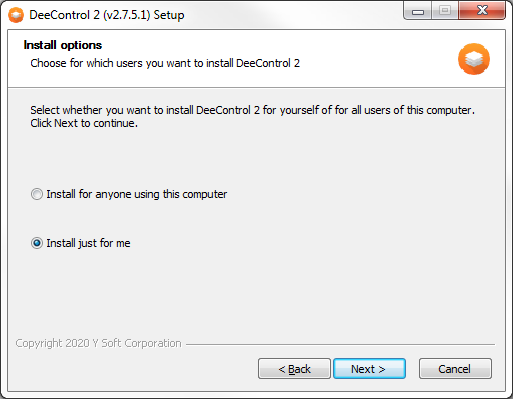
- Select whether you want to install DeeControl 2 for yourself or for all users of the computer.
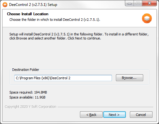
- You can change the installation directory. If selected directory already exists, a notification that contents of the directory will be deleted is shown.
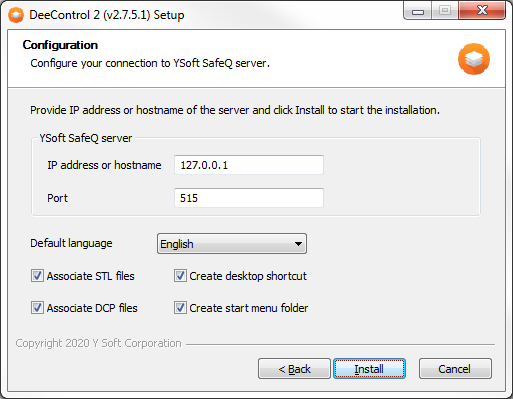
- You can setup your Dispatcher Paragon server address and port. You can also set default language or check a check box if you want to create a desktop shortcut, start menu folder, or associated STL files.
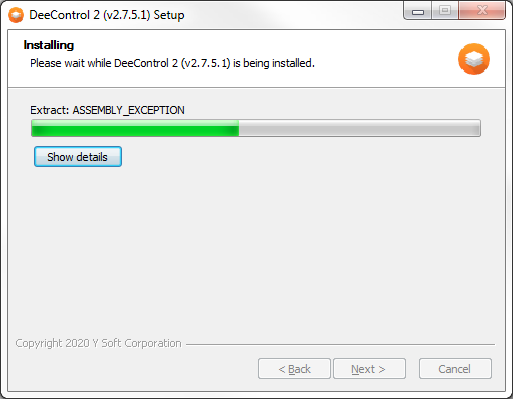
- The installation's progress displays.
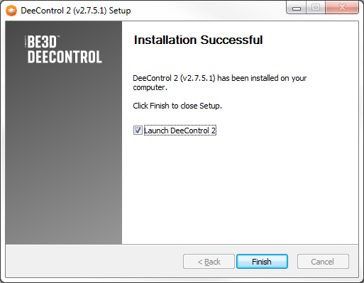
- Once the installation is successful, a confirmation message displays. You can check a check box if you want to run DeeControl 2 right after the installation wizard closes.
Windows Silent Installation
The installation can run from a command line in silent mode, which allows the installation of DeeControl2 on remote computers or via an installation script. To enable silent installation, run the installation file with the /S parameter
Setup parameters
- /SQaddr
- sets the Dispatcher Paragon server address
- e.g.: /SQaddr=10.0.0.1
- /SQport
- sets the Dispatcher Paragon server port
- e.g.: /SQport=515
- /Shortcut=true
- enables the creation of a desktop shortcut
- /StartMenu=true
- enables the creation of a start menu folder
- /AssociateStl=true
- registers STL files to be opened by DeeControl 2
- /AssociateDcp=true
- registers DCP files to be opened by DeeControl 2
- /StartUpLocale=en_US
- sets default language of DeeControl 2
- possible values:
- en_US (English)
- cs_CZ (Czech)
- da_DK (Danish)
- es_ES (Spanish)
- nb_NO (Norwegian)
- nl_NL (Dutch)
- /D
- sets the destination folder of the installation
- e.g.: /D=C:\Program Files\DeeControl 2
- CAUTION: It must be the last parameter used in the command line and must not contain any quotes, even if the path contains spaces. Only absolute paths are supported.
Example
deecontrol-win-installer.exe /S /SQaddr=127.0.0.1 /SQport=515 /Shortcut=true /StartMenu=true /StartUpLocale=en_US /D=C:\Program Files\DeeControl 2Windows Uninstallation
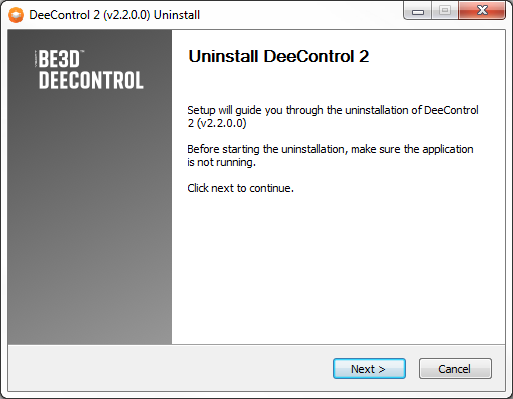
- Run the unistallation file and follow the wizard.
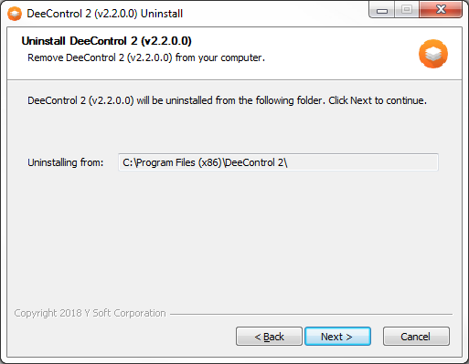
- Confirm the directory to uninstall from.
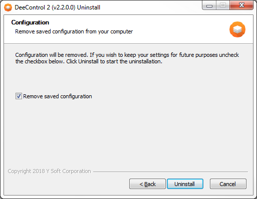
- Check if you want to remove your configuration.
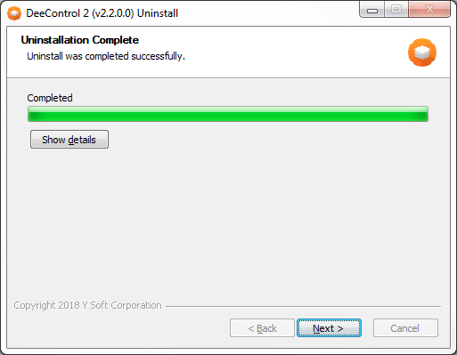
- Wait until the uninstallation is complete and click Next.
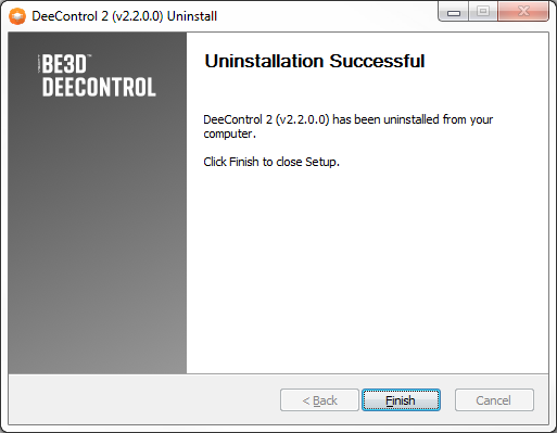
- The uninstallation is finished.
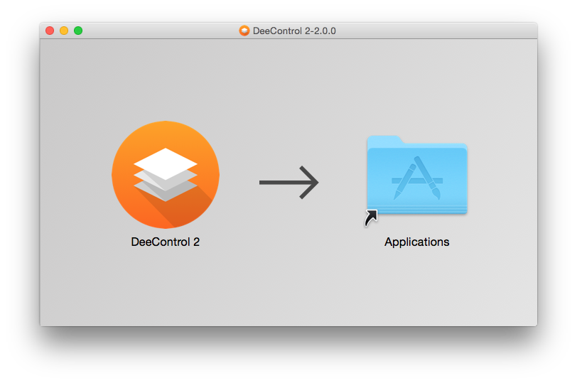
Mac Installation
Once you have opened the DMG file, the only thing needed to install DeeControl2 on your Mac OS is to drag and drop the DeeControl2 icon onto the Applications icon.
How to Set Up a connection to Dispatcher Paragon Server
In the Windows version of the DeeControl 2 installer, the connection to Dispatcher Paragon server can be set during installation (step 5 in section Windows Installation, or appropriate parameters in section Windows Silent Installation).
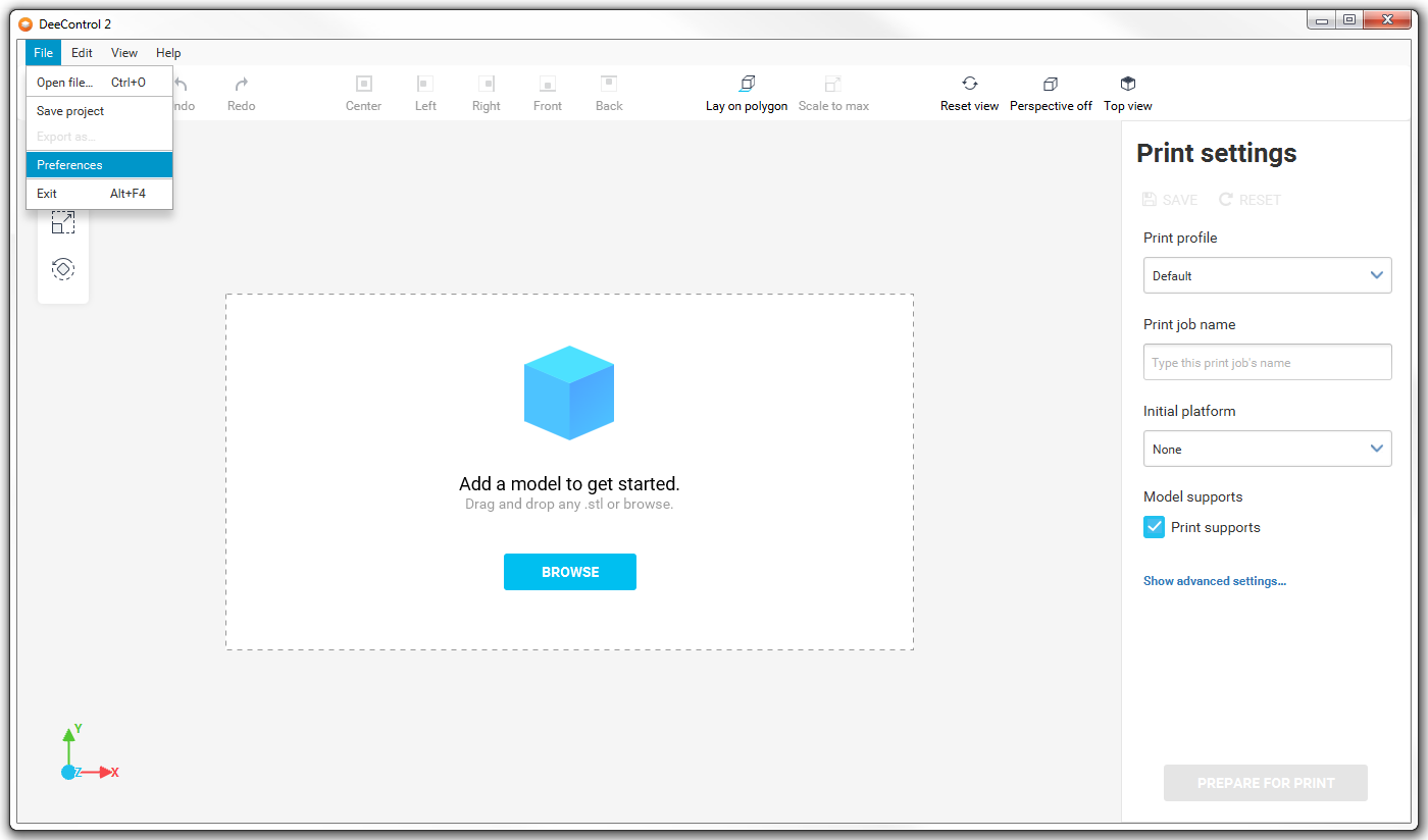
- Open the preferences window by clicking the Preferences button in the File menu.
- Switch to the NETWORK tab in the preferences window. Set the Dispatcher Paragon server address and port, then click SAVE button to store your settings or CANCEL to discard your changes.
In Dispatcher Paragon username field you can specify a user who will be owner of a print job sent to Dispatcher Paragon, so you are able to send print jobs from your device and they will be associated with your Dispatcher Paragon account. If you left the field empty, your system username will be used automatically.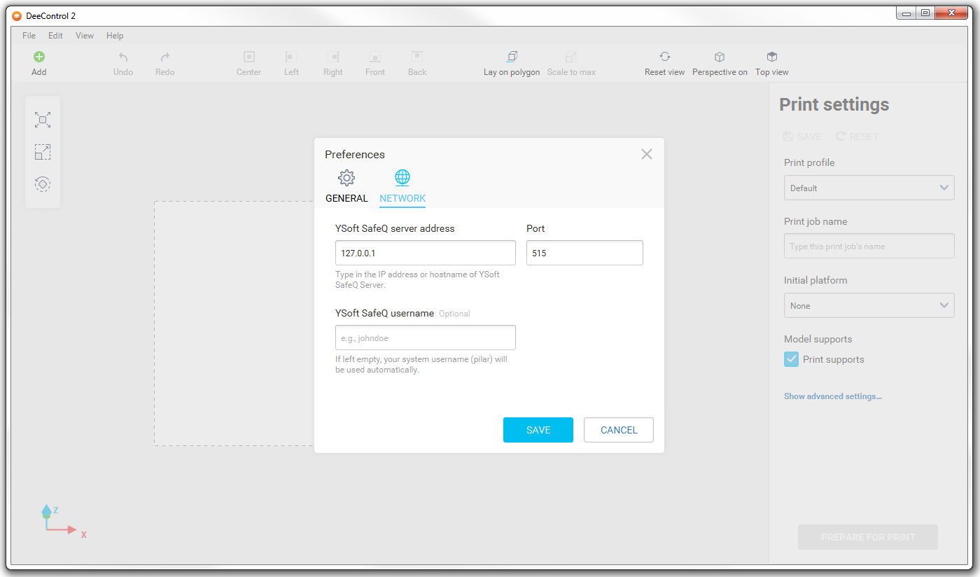
Select language
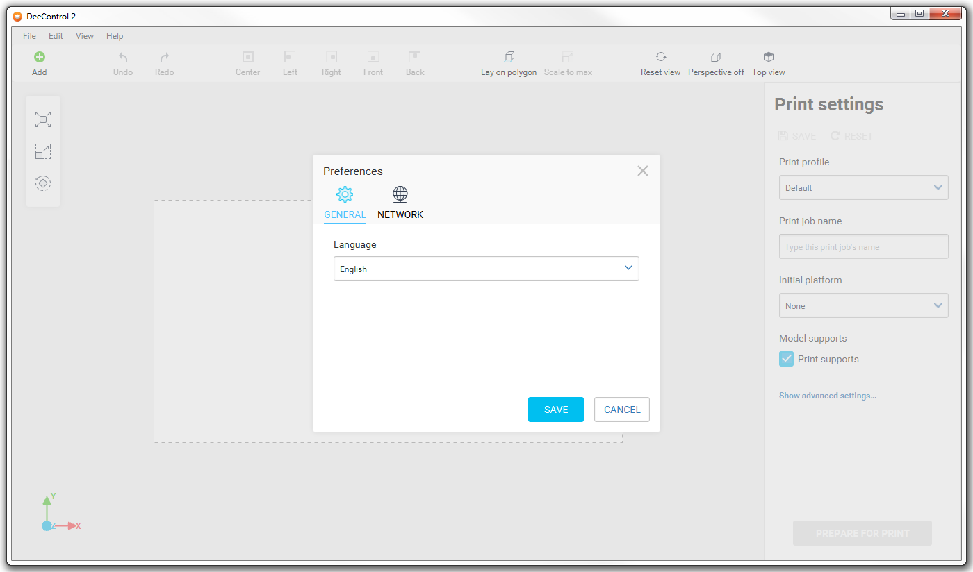
- Open the preferences window by clicking the Preferences button in the File menu.
- Switch to the GENERAL tab in the preferences window. Select your preferred lanaguage, then click SAVE button to store your settings or CANCEL to discard your changes.
Print Job Preparation
DeeControl 2 only supports STL 3D model files.
- Open the STL file using one of the following methods (multiple files can be opened at once):
- Use the open file dialog
- Drag and drop – drag the STL file and drop it onto the DeeControl window
- Double-click the STL file
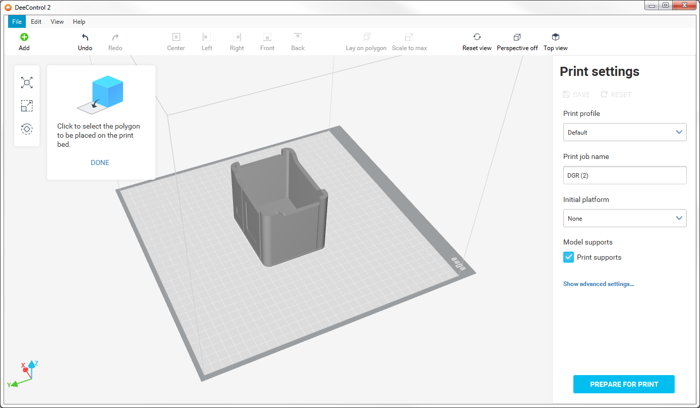
- Edit the model to fit your needs.
- Move
- You can move your model by dragging it using a mouse.
- You can use the predefined buttons in the main bar to center your model or align the model to the edges of the printable area.
- You can set the exact coordinates of the center of the model using the input fields in the move panel.
- Scale
- You can scale your model to the maximum size allowed by the print bed and the selected settings (e.g., the initial platform reduces the area that can be used for printing the model) using the SCALE TO MAX button in the scale panel or corresponding button in main bar.
- You can set the exact scale of the model using the input fields in the scale panel.
- Rotate
- You can rotate your model by axes that are relative to the print bed using the input fields in the rotate panel. Choose the axis and enter the angle by which you want to rotate the model. Then click one of the buttons alongside the input field to rotate clockwise (right) or counterclockwise (left).
- You can reset the model's rotation using the RESET button in the rotate panel.
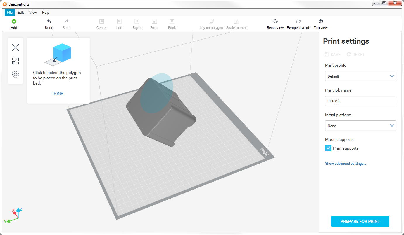
- You can lay your model on specific face by using LAY ON POLYGON button in rotate panel or corresponding button in main bar.
- Move
Lay model on selected face
Use mouse to select a face and click. Your model will be rotated so the selected face will be laid on print bed.
Using 3D Viewport
For easier preparation of the model or viewing a GCode visualization, you can rotate, pan, or zoom the view. It is possible to turn off the perspective to view the alignment of the models on print bed better or the GCode lines in layers.
View Mode
View mode can be switched using the perspective switch button in the main bar.
- Perspective
- Displays scene of the print area as seen by the human eye.
- Parallel
- In this mode, all parallel lines are displayed parallel even if they are heading away from the camera.
Controlling the View
The view can be reset using the Reset view button in the main bar.
- Rotate
- To rotate the view, use the left mouse button.
- For a better view of the model's placement, there is the Top view button in the main bar.
- Pan
- To pan the view, use the right mouse button.
- Zoom
- To zoom the view, use the mouse wheel.
DeeControl 2 project
DeeControl 2 project can be used for saving your unfinished work or to share your scene setup and print settings with someone else.
To save current scene and print settings click the Save project button in the File menu.

To load the saved project you can use the same methods as for loading a STL file.
- Open the file dialog from file menu (select DCP extension as type)
- Drag and drop
- Double click on file (if associated)
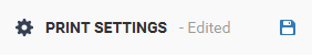
Print Settings
The properties of the final printout can be further modified using the print settings.
Basic Settings
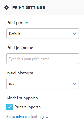
- Print profile
- Default – a balanced profile that prints most models without any problems.
- Speed print – a good choice when you want to print fast but the quality is not an issue.
- Fine quality print – the printed model will have a smoother shell but it will take more time to print.
- Print job name – select the name of your print job displayed in Dispatcher Paragon. The name of the first model imported into the scene is used as the default name.
- Initial platform – the initial platform takes up some of the space of the print area, so the model cannot cover the whole print bed.
- Brim
- Raft
- None
- Model supports
- Print supports
Advanced settings
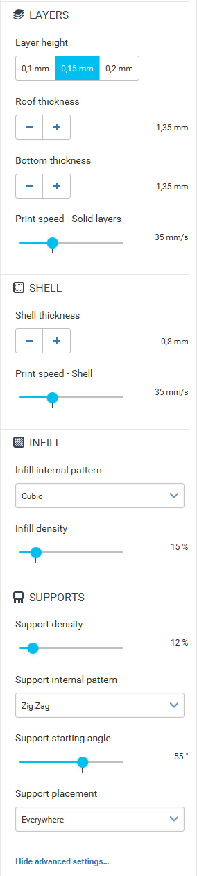
- Layer height – the lesser the value, the finer the surface is.
- 0.1 mm; 0.15 mm; 0.2 mm
- Roof thickness – the thickness of the top side of the model.
- 0 mm and greater
- Bottom thickness – the thickness of the bottom side of the model.
- 0 mm and greater
- Print speed – Solid layers – the speed of the print head movement when printing the roof and bottom layers. A higher speed may have a negative impact on the quality of your print.
- Shell thickness – the thickness of the walls of the model. The higher the value, the stronger the model is.
- 0–4 mm (multiples of the nozzle diameter – 0.4 mm)
- Print speed – Shell – the speed of the print head's movement when printing the shell. A higher speed may have a negative impact on the quality of your print.
- Infill internal pattern – a geometric shape repeated on the inside of the model to add strength to the model.
- Grid
- Line
- Cubic
- Infill density – the density of the internal structure. A higher density significantly slows the print down but results in a harder model.
- Support density – the density of the support structure. A higher density results in better overhangs but the support structure is harder to remove.
- Support internal pattern – a geometric shape repeated on the inside of the support structure to add strength to it.
- Lines
- Grid
- Zig Zag
- Support starting angle – the maximum angle of overhangs for which the supports will be printed.
- 0° (supports everywhere) – 90° (no supports)
- Support placement – indicates where support structures should be generated
- Everywhere
- Touching build plate only
- Everywhere
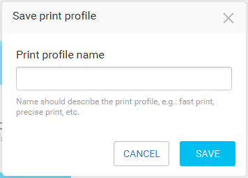
Saving a Print Profile
If any of the previous settings are changed, a new profile can be saved by clicking the floppy disk icon on the right-hand side of the print settings header and filling the profile name in the following dialog.
Preparing a Model for Print
When you have prepared your models and chosen the fitting settings, it is time to click the PREPARE FOR PRINT button in the right panel.
![]()
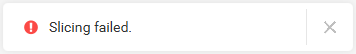
If something goes wrong during slicing, the following alert displays.
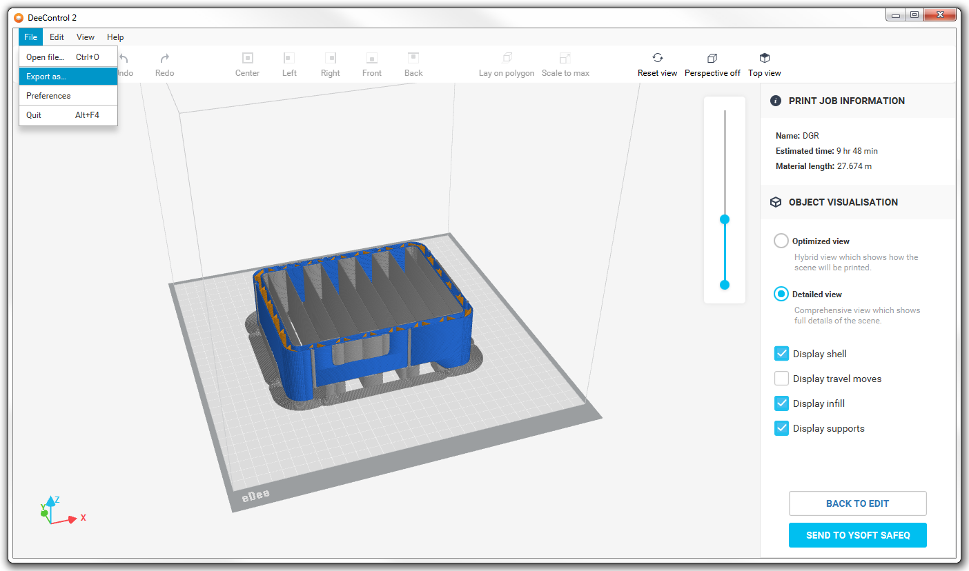
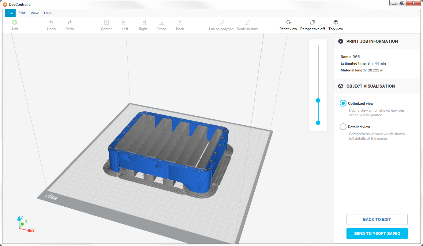
Viewing GCode and Sending the Print Job to the Dispatcher Paragon Server
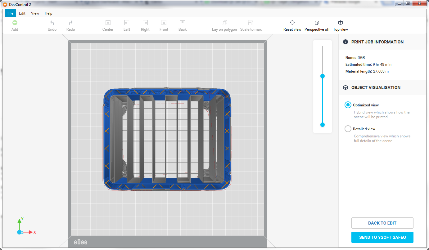
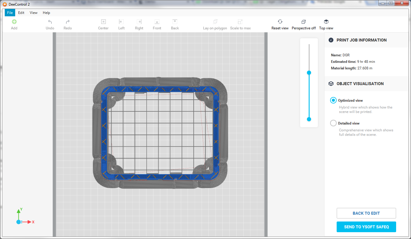
For a better idea of how the print will look, you can use a GCode visualizer. On the right side of the workspace, you have a slider that is used to select the visible part of the print job. To determine if all the lines are aligned as you wish, the perspective switch can be turned off as shown on the images below (left – perspective on; right – perspective off).
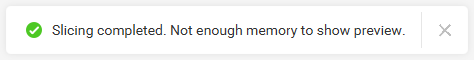
It is possible you do not have enough memory to view the vizualisation of GCode. In that case, a notification (image below) displays but you can still upload your print job to the Dispatcher Paragon server.
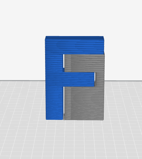
Viewing a Specific Part of GCode
If you want to view a specific part of GCode such as shell, infill, or supports, you can switch to Detailed view.
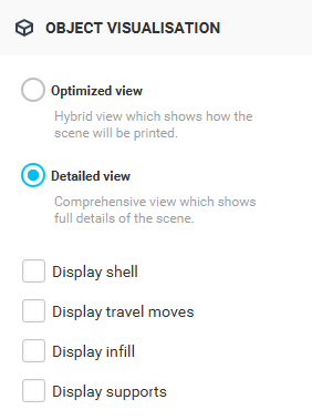
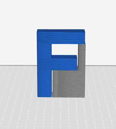
- Shell – the part of the model that is outside. (blue)
- Travel moves – the movements made by the print head without extruding filament. (red)
- Infill – the part of the model that is inside. (yellow)
- Supports – the part of the print that should be removed after the print is finished. (grey)
Sending to the Dispatcher Paragon Server
After you are satisfied with the print job, you can use the SEND TO YSOFT SAFEQ button at the bottom right-hand corner to upload your print job.
If you have not configured the connection details of the Dispatcher Paragon server, an alert appears as shown in the image below. Click the SHOW link to open the Network preferences and set up your connection (see section How to Set Up a connection to Dispatcher Paragon Server).

Exporting the Print Job
You can export the print job as two file types GCODE and 3DJOB. The GCode file can be used for some debug analyses. The 3djob should be used to manually upload to the Dispatcher Paragon server in the future. To export, use the "Export as…" item in the File menu.